
 Español
 Türkçe
 Français
 عربي
عربي  dansk
dansk 한국어
한국어 Deutsch
 Việt Nam
 Italiano
 日本語
日本語 Português

Critical limitation: "AR500" is a commercial hardness class, not a complete welding specification. Before welding, obtain the plate MTC and the manufacturer's welding guidance. Plate chemistry, carbon equivalent, thickness, heat treatment, joint restraint, ambient temperature, and consumable hydrogen level can materially change the correct procedure.Critical limitation: "AR500" is a commercial hardness class, not a complete welding specification. Before welding, obtain the plate MTC and the manufacturer's welding guidance. Plate chemistry, carbon equivalent, thickness, heat treatment, joint restraint, ambient temperature, and consumable hydrogen level can materially change the correct procedure.
Can You Weld AR500 Steel?
Yes, AR500 wear plate can be welded successfully. The important qualification is that the weld procedure must protect both the joint and the wear plate around it. AR500 is normally supplied in a quenched-and-tempered condition with a nominal hardness around 500 HBW. It delivers excellent abrasion resistance, but it is less forgiving than mild steel when a joint cools too quickly, carries high restraint, or absorbs hydrogen from damp consumables, moisture, oil, rust, or frost.
The objective is not simply to make a weld that looks sound. A robust AR500 welding procedure controls three competing outcomes: cold-cracking risk, heat-affected-zone softening, and residual stress. Too little preheat or poor consumable control can create delayed hydrogen cracking. Too much heat input or excessive interpass temperature can soften the adjacent wear plate, reducing the service life in the exact area that is expected to resist abrasion.
For this reason, AR500 should never be welded from a generic "high-carbon plate" rule of thumb. Treat the plate manufacturer's data, the job-specific WPS, and the MTC as governing documents. If the wear plate is being welded into a safety-critical, fatigue-critical, lifting, pressure, or highly loaded structure, involve a qualified welding engineer before production starts.
Why AR500 Welding Requires More Control Than Mild Steel
|
Welding variable |
Why it matters on AR500 |
Practical control |
|
Plate condition |
AR500 obtains wear resistance from controlled quench-and-temper processing. Excessive local heating can change the microstructure adjacent to the weld. |
Limit heat input, respect maximum interpass temperature, and keep welds out of primary wear zones where design permits. |
|
Hydrogen |
Diffusible hydrogen plus a hard heat-affected zone plus tensile stress is the classic cold-cracking combination. |
Use dry low-hydrogen consumables and clean, dry joint faces. |
|
Cooling rate |
Heavy plate, cold weather, and strong heat sinks can pull heat from the joint quickly. |
Use the specified minimum preheat and maintain it through the root and fill passes. |
|
Joint restraint |
A highly restrained assembly cannot shrink freely after welding. Residual stress rises sharply. |
Use sensible sequencing, balanced welds, smaller practical weld sizes, and avoid corners for starts/stops. |
|
Wear-zone location |
A structural weld in the sliding wear zone becomes the first area to wear away. |
Relocate the joint, add a replaceable liner, or use a qualified buffer-plus-hardfacing system. |
Step 1: Confirm What "AR500" Actually Means on Your Job
Do not assume that every AR500-branded or AR500-described plate has the same chemical composition or welding behavior. AR500, NM500, XAR 500, Hardox 500, and other 500 HBW-class materials can have similar hardness ranges but are not automatic substitutions. Their permitted plate thicknesses, carbon equivalent values, guaranteed impact properties, and welding limits may differ.
Collect the MTC for the actual plate heat and verify grade, thickness, heat number, hardness range, chemistry, carbon equivalent (CEV or CET), and delivery condition.
Identify the material on the other side of the joint. When AR500 is joined to mild steel, HSLA steel, cast steel, or a worn existing component, the most restrictive material and joint condition often governs the WPS.
Define the joint function: structural load transfer, attachment weld, liner retention, crack repair, hardfacing overlay, or a temporary field repair. These uses do not require the same filler metal or acceptance criteria.
Confirm whether the weld or heat-affected zone will sit in the material flow path. If it will, redesigning the liner layout may be more valuable than choosing a harder weld metal.
Step 2: Set Preheat and Interpass Temperature Correctly
There is no universal AR500 preheat temperature. A correct temperature is selected from the actual plate manufacturer's data or from a qualified WPS, then adjusted for the joint. Manufacturer guidance for comparable 500 HBW wear plate shows that required preheat and interpass temperature rise with plate thickness; damp or cold conditions can require a further increase. This is why copying a single "200°C for all AR500" instruction is unsafe.
Use this calculation workflow before production welding:
1. Use the governing single-plate thickness. For unequal plate thicknesses of the same material, use the thicker plate; for dissimilar joints, assess both materials and use the more demanding result.
2. Review plate chemistry and CEV/CET on the MTC. Higher hardenability, thicker plate, lower ambient temperature, and higher restraint all push the procedure toward more preheat control.
3. Select the welding process and consumable class. Confirm the consumable's diffusible-hydrogen rating and storage requirements, not merely the tensile-strength designation.
4. Calculate nominal heat input: Q = (eta x U x I x 60) / (1000 x travel speed), where Q is kJ/mm, eta is thermal efficiency, U is voltage, and I is current. Record the actual parameter range in the WPS.
5. Choose the minimum preheat and maximum interpass temperature from the plate manufacturer's table or the qualified WPS. Measure at the specified distance from the prepared joint after the plate has equalized in temperature.
6. Run and inspect a production-representative test coupon when the material source, thickness, repair history, restraint, or loading differs from the qualified procedure.
|
Planning scenario only |
Conservative starting discussion range |
What can push the requirement upward |
|
Thin to medium AR500 plate, low restraint, dry low-hydrogen consumables, indoor work |
75-125°C (167-257°F) |
High CEV/CET, cold plate, damp atmosphere, poor fit-up, multiple passes, or heat sink from a thick attachment. |
|
12-25 mm plate or moderate restraint |
100-150°C (212-302°F) |
Thick mild-steel support, double-V geometry, heavy repair build-up, restrained corners, or high residual stress. |
|
Above 25 mm, high restraint, repair welding, cold outdoor conditions |
150-200°C (302-392°F) only if supported by the plate data / WPS |
Unknown chemistry, cracking history, severe restraint, or low heat input on a thick heat sink. |
Measurement practice: Heat a broad band around the planned joint rather than a narrow line. Check temperature on the parent plate near the joint, not only in the hot weld pool. Do not begin welding until the required preheat has equalized through the joint area. Maintain the procedure-defined interpass window, then allow controlled still-air cooling unless the qualified WPS specifies otherwise.
Step 3: Choose Filler Metal for Ductility and Crack Resistance
The filler metal does not always need to match the hardness or tensile strength of AR500. For many attachments, liner joints, and general fabrication welds, an undermatched low-hydrogen weld metal is deliberately chosen because it gives a more ductile joint that can absorb shrinkage stress. The appropriate choice depends on load, service temperature, fatigue demand, base-metal pairing, and whether the weld itself will be exposed to abrasion.
|
Joint / repair situation |
Common filler strategy |
Important note |
|
AR500 to mild steel or HSLA attachment, general static loading |
Low-hydrogen unalloyed or low-alloy consumable in the E70/E80 strength family, selected and qualified for the joint. |
A lower-strength, tougher weld can be preferred to a brittle hardness match. Verify required tensile and impact properties. |
|
GMAW / FCAW production welding |
Low-hydrogen wire or flux-cored system with manufacturer-controlled storage and shielding-gas procedure. |
The wire label alone is insufficient; confirm actual diffusible hydrogen performance and gas condition. |
|
Dissimilar joint, unknown repair chemistry, or buffer under hardfacing |
Austenitic stainless buffer consumable such as AWS 307 or 309 class where permitted by the qualified procedure. |
A buffer layer can improve crack tolerance, but it is not automatically suitable for high-temperature, fatigue-critical, or corrosion-specific service. |
|
Wear restoration / hardfacing |
Tough buffer layer first; hardfacing alloy only on top where wear requires it. |
Do not use hardfacing consumable as the primary structural joining weld unless a welding engineer specifically qualifies it. |
When the weld is inside a high-wear area, a two-layer approach is often better than attempting to use a single very hard weld deposit. First make the structural or buffer layer using a crack-tolerant, tough consumable. Then apply the qualified hardfacing overlay. This protects the joint from abrasive loss while avoiding a brittle structural weld deposit.
Step 4: Prevent Hydrogen-Induced Cracking
Hydrogen cracking can be delayed. A weld may look acceptable at shift end and still crack hours later as the joint cools and residual stress concentrates. Prevention requires a system, not a single preheat number.
|
Risk source |
Preventive action |
|
Damp electrodes, flux, or wire |
Use manufacturer-approved storage, rebake, and holding practice. Keep consumables out of open humid air. |
|
Moisture, oil, paint, rust, frost, or dirt |
Grind and clean a sufficiently wide band on both sides of the joint. The joint must be dry before preheat begins. |
|
Cold plate / rain / high humidity |
Shelter the work where practical. Raise preheat according to manufacturer guidance or WPS and keep the temperature stable through the root pass. |
|
High restraint and oversize welds |
Reduce weld volume, use balanced sequence, relocate starts/stops away from corners, and avoid unnecessary full-length welds where the design allows. |
|
Wide root gap or poor fit-up |
Correct fit-up before welding. A large gap forces excess weld metal and high restraint into the joint. |
|
Rapid cooling after welding |
Avoid water, compressed-air quenching, snow, or cold wet surfaces. Let the joint cool uniformly under the qualified procedure. |
Five Common AR500 Welding Mistakes
1. Treating AR500 Like A36 or Ordinary Carbon Plate
A mild-steel procedure may produce an acceptable-looking bead yet fail to control the hard heat-affected zone or hydrogen level. The correction is simple: start from the actual wear-plate MTC and a procedure qualified for the joint, not from a general shop default.
2. Choosing Filler Only by "Match the Plate Strength"
Matching AR500 hardness with a very hard weld deposit can make cracking more likely. In many structural attachment joints, a tougher, lower-strength low-hydrogen filler produces a more reliable connection. Strength matching should be selected for actual service requirements, not assumed from the plate name.
3. Excessive Heat Input or Interpass Temperature
More heat is not automatically safer. Excessive heat widens the heat-affected zone, increases distortion, and can soften the surrounding wear plate. Use only the heat input needed for fusion and the WPS-defined bead profile. Record amperage, voltage, and travel speed instead of relying on visual judgement alone.
4. Poor Consumable and Surface Condition
Damp electrodes, wet flux, contaminated shielding gas, grease, and frost introduce hydrogen exactly where AR500 is least forgiving. Consumable control and joint cleaning are low-cost controls with a high impact on reliability.
5. Welding a Highly Restrained Repair in One Long Continuous Pass
Repairs often fail because the component cannot move as it cools. A long high-deposition bead may pile shrinkage stress into a cracked area. Re-plan the repair, remove damaged material completely, preheat broadly, use a balanced sequence, and stop to verify temperature and fit-up between stages.
Field Repair Procedure for a Cracked or Worn AR500 Component
Safety / quality gate: Do not repair a crack in a lifting component, pressure-retaining item, safety guard, crane structure, or fatigue-critical machine frame from a generic online procedure. Those cases require formal engineering disposition and an approved WPS/PQR.
1. Isolate and assess the component. Record location, crack length, plate thickness, loading direction, wear pattern, and whether the crack reaches a structural attachment or a highly stressed corner.
2. Identify the material and repair history. Obtain the MTC where available. If chemistry is unknown, treat the repair as elevated risk and obtain engineering guidance before welding.
3. Remove the crack and damaged metal completely by the approved mechanical or thermal method. Do not weld directly over a crack. Prepare a clean groove with smooth transitions; avoid sharp notches and abrupt section changes.
4. Inspect the prepared area using an appropriate method such as visual inspection plus magnetic-particle testing where applicable. Confirm the crack has been fully removed before depositing weld metal.
5. Set broad preheat and maintain the required interpass temperature. Use dry low-hydrogen consumables and the qualified heat-input range.
6. Weld in short, balanced passes. Sequence from rigid areas toward free edges where practical. Do not use compressed air or water to accelerate cooling.
7. Inspect after cooling. For critical repairs, use the acceptance method specified by the drawing, owner, or repair procedure. Recheck after a hold period when delayed cracking is a concern.
8. Restore wear protection separately. Where abrasion is severe, apply a compatible buffer layer and qualified hardfacing, or install a replaceable liner so that future wear does not consume the structural repair.
AR500 Welding Checklist Before the Arc Starts
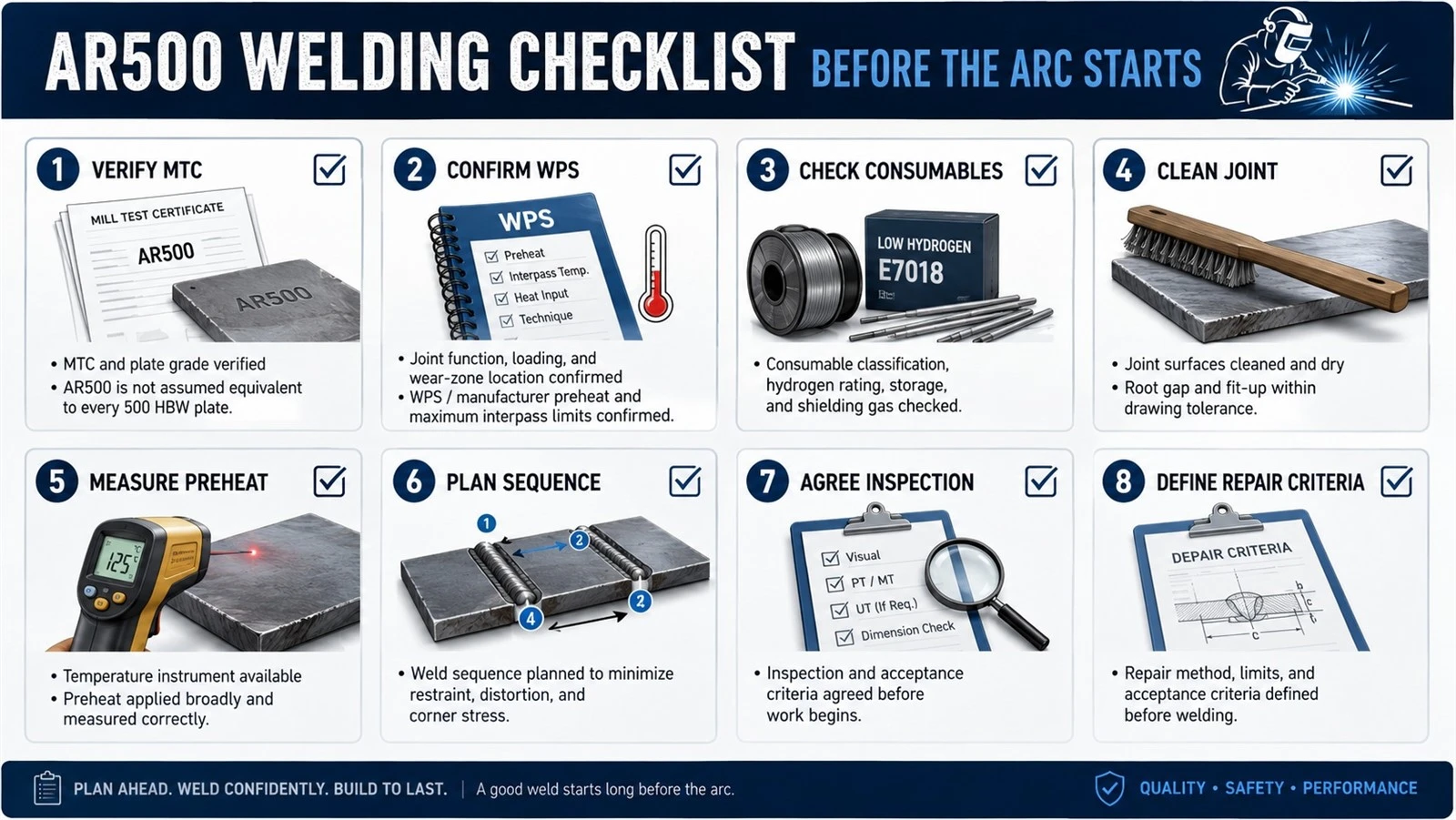
- MTC and plate grade verified; AR500 is not assumed equivalent to every 500 HBW plate.
- Joint function, loading, and wear-zone location confirmed.
- WPS / manufacturer preheat and maximum interpass limits confirmed.
- Consumable classification, hydrogen rating, storage, and shielding gas checked.
- Joint surfaces cleaned and dry; root gap and fit-up within drawing tolerance.
- Temperature instrument available; preheat applied broadly and measured correctly.
- Weld sequence planned to minimize restraint, distortion, and corner stress.
- Inspection and repair acceptance criteria agreed before work begins.
FAQ
Q: What preheat temperature should I use for AR500?
A: Use the plate manufacturer's published welding table or a qualified WPS. As a planning discussion only, many AR500 joints fall into a 75-200°C range depending on thickness, chemistry, restraint, ambient conditions, and consumable hydrogen level. Do not use one fixed temperature for every plate.
Q: Can I weld AR500 with E7018?
A: A low-hydrogen E7018-family electrode may be suitable for some AR500-to-mild-steel or attachment joints when the procedure is properly qualified. The choice must still satisfy the loading, toughness, hydrogen-control, and preheat requirements of the actual joint.
Q: Should filler metal match the 500 HBW hardness?
A: Usually no. A hard matching deposit can be brittle. For many joints, a tougher, undermatched low-hydrogen weld metal is preferred. Use hardfacing only where abrasion requires it, typically over a tough buffer or structural layer.
Q: Can AR500 be hardfaced?
A: Yes, but use a system approach: correctly weld the base joint, apply a compatible buffer layer where required, then apply the hardfacing overlay. High hardfacing preheat requirements must not exceed the base plate's allowed interpass limits.
Need NM500 or AR500 Plate with Full MTC and Welding Data?
Promisteel supplies NM500 wear resistant steel plate with heat-specific mill test certificates, carbon equivalent data, and manufacturer welding guidance - the documents you need before production starts.
Request a Quote →


